
Flyback Converter Clamp with Slow Recovery Diode
Conventional RCD clamps used for Flyback drain clamp use fast recovery diodes - what happens when you use a slow recovery part?
Flyback Converter Drain Spike
Flyback converters are a simple power converter topology that use one switch and a coupled inductor to create step-up, step-down, and multiple output supplies. However, flybacks have an issue that must be dealt with: the turn-off voltage spike at the switch drain. Leakage inductance in the coupled inductor behaves like an inductance in series with the switch. At turn-off, current continues to flow in the leakage inductance. The resulting voltage spike at the switch drian must be clamped, or the switch will avalanche. There are couple of ways to do this, the most common of which is an RCD clamp.
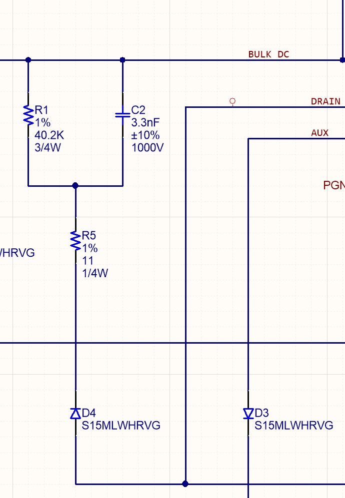
RCD Clamp Circuit with Series Damping Resistor
The RCD Clamp
The RCD voltage clamp works by conducting leakage energy through the diode, storing it in the cap, and discharging the cap with the bleed resistor. The conventional approach is to make the snubber cap large enough so that it stays at a relatively constant voltage. The resistor is sized to hold the cap at the desired clamp voltage. The diode is selected to clamp very fast to minimize reverse recovery charge. All the leakage energy is captured in the capacitor and bled by the resistor. Below is a plot of drain and cap voltage using conventional RCD clamp. It uses an 11 ohm series damping resistor, but clearly will require even more damping.
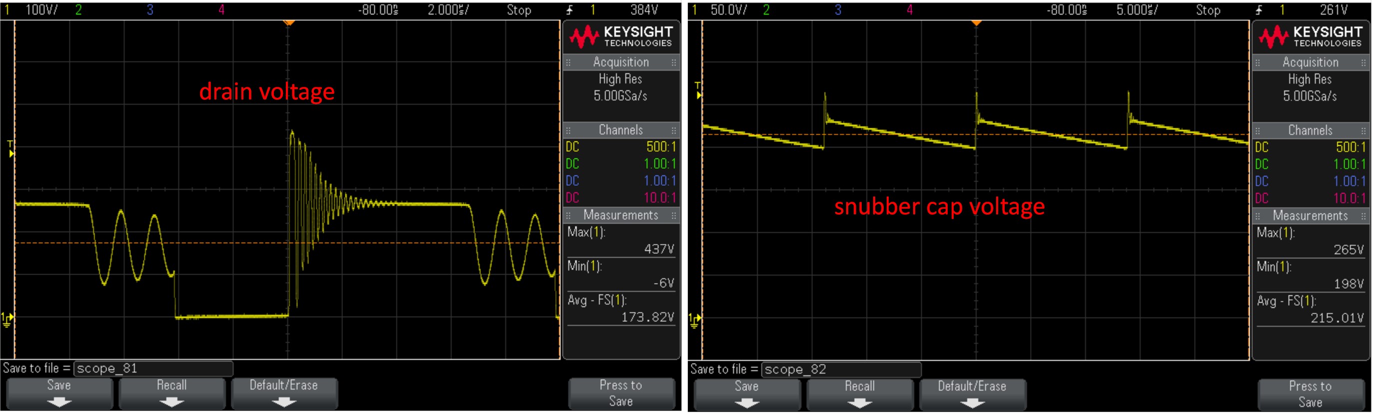
*Drain and cap voltages with conventional RCD clamp + series damping *
Alternate Approach - RCD with Slow Recovery Diode
Why use a slow diode? Won't it increase losses? make more EMI? How will it capture all the leakage energy in the snubber cap? Well, it turns out that when you use a slow diode, it still clamps the drain node voltage, but the behavior is a different (in a good way). When you clamp with a slow diode, you only temporarily store the leakage energy in the snubber cap. Once the cap voltage peaks, current flow reverses in the still-conducting diode. Though the reverse current flow through the diode is a lossy process, current is flowing back into the primary winding to be recycled!
Try it out!
After looking at a number of reference designs from Diodes and Power Integrations using slow diodes, I wanted to try it out for myself. It took some experimentation to get it right. A smaller cap value is required than would be with a conventional approach. This is because you are not going for a constant voltage in the snubber cap. Cap voltage will start near the reflected voltage and rise quickly to the clamp voltage before falling back to near the reflected voltage again. The bleed resistor and target voltage on the snubber cap needs to change also. The clamp voltage is tuned by changing the snubber capacitance rather than the bleed resistor. The bleed resistor now just needs to bleed the residual energy that is not cycled back to the input.
The results are in...
When it’s tuned, there is little ringing on the drain node and power dissipation in the bleed resistor goes down significantly. The plot below shows drain and cap voltages with no series damping resistor.
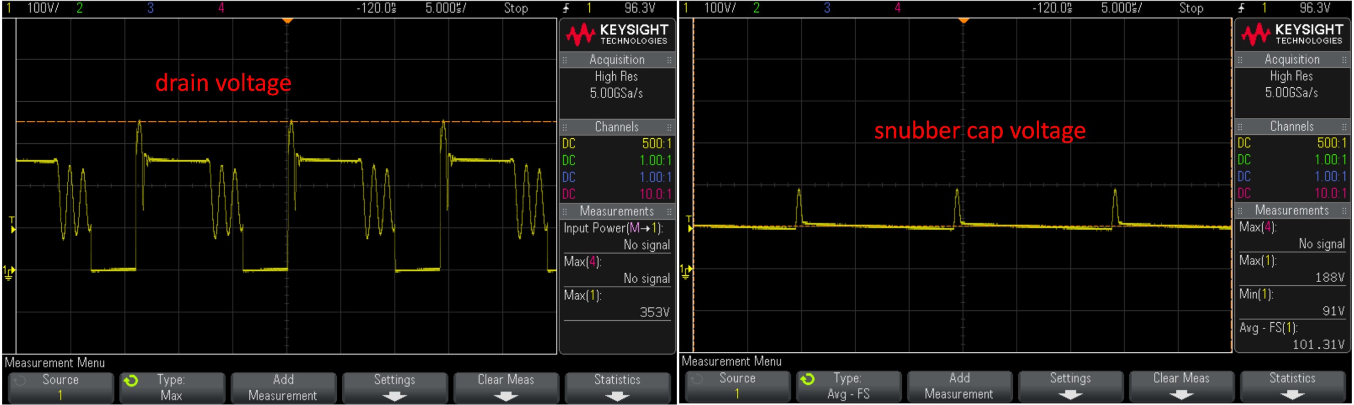 *Drain and cap voltages with slow recovery RCD clamp with no series damping *

By: Dave
Dave is skilled in circuit design, PCB layout, and EMC - specializing in automotive power electronics hardware design. In addition to 10+ years as an electronics consultant, Dave spent his career in the automotive industry from engineering to upper management. Dave is a registered Professional Engineer (Mechanical). He also holds a MS in Computer Science (Laurence Tech 06') and a BS in Mechanical Engineering (GMI 86').
Like what you see?
Experiments
About Us
DEB Associates helps companies through the entire electronics design process. Our team is smart, reliable, and deeply knowledgeable about the intricacies of circuit design, PCB layout, and EMC.
DEB Associates 2020